There are a number of acceptable calculation methods for determining U-Factors, and the appropriate method depends on the type of framing or discontinuity in the wall. Heat flow through construction assemblies with metal framing and/or sheathing is more complex and requires special consideration. The following table shows the acceptable calculation methods that can be used with each type of construction.
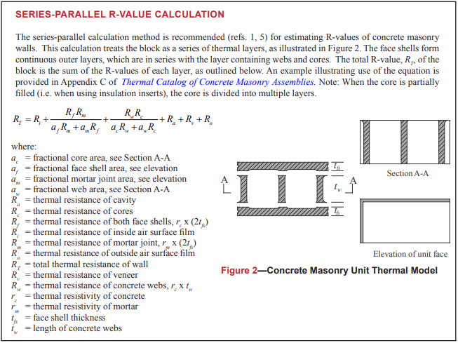
U-Factor Analysis for Single Wythe: Series-Parallel Method Examples
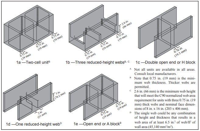
Fully Grouted 3-web Series-Parallel Analysis Example
Task: Find the R-value and U-factor for a 3-web fully grouted CMU block following a Series-Parallel R-Value Calculation.
Fully Grouted 2-web Series-Parallel Analysis Example
Task: Find the R-value and U-factor for a 2-web fully grouted CMU block following a Series-Parallel R-Value Calculation.
Analysis of effect of reduced block webs and core insulation
Task: Compare the R-value and U-factors of a 2-web fully grouted CMU block vs 3-web fully grouted CMU block.
Comparisons of hand calculations and tabled values from the NCMA Thermal Catalog (www.ncma.org) are also made. Effects of integral foam core insulation and exterior insulation board are also presented.
More Information on the thermal resistance can be found in the Thermal Catalogue (NCMA.org)
Thermal Bridging
Thermal bridging can significantly increase the amount of heat flow through the building envelope, especially when metal elements bridge through insulation like metal studs. Typical metal studs can reduce wall cavity insulation effectiveness by 40 to 70 percent. Typical anchors and ties in masonry wall systems, even where they extend through insulation in the drainage cavities, do not have a significant effect of energy usage and generally ignored.
Another masonry wall element that can cause thermal bridging are steel shelf angles in multi-wythe masonry walls. The thermal bridging effects of these elements can addressed by providing additional insulation in the masonry drainage cavity. The zonal method (a modification of the series and parallel analysis methods) should be used when determining the assembly U –factors. It should also be noted that holistic building energy analysis would suggest that this thermal bridging does not significantly impact the yearly energy use for most common configurations.
Further discussion of this thermal bridging is presented in Tek Note 06-13-B. Further guidance for thermal bridging in masonry will also be available the standard, “Mitigation of Thermal Bridges for Buildings having Concrete and Masonry Walls, or Masonry Veneer”, ACI 122.Y. American Concrete Institute, 2021.
TEK 06-13B Thermal Bridges in Wall Construction
This TEK Notes gives a great summary and introduction of the concepts of thermal bridging discussing its causes, effects, and requirements within differing masonry walls.