Steady-state heat flow assumes that temperatures on both sides of a building envelope element (while different) are constant for a sufficient period of time that heat flow on both sides of the assembly is steady. The steady-state heat flow method is a simplification, because in the real world, temperatures change constantly. However, this method can predict average heat flow rates over time and is used by ASHREA Standard 90.1 to limit conductive heat losses and gains. Heating and cooling equipment is commonly sized using the steady state heat flow in and out of a building during peak conditions. As they are easy to understand and use, many codes limit the steady state heat flow.
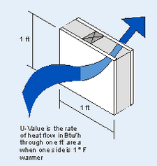
U-Factor: The U-Factor defines the rate of steady-state heat flow. It is the amount of heat, typically in Btu’s (British thermal units) that flow each hour through one square foot of an assembly, when there is a one-degree temperature difference between the inside air and outside air. The heat flow can be in either direction, as heat will flow from the warmer side to the cooler side.
Each layer of a building assembly (such as sheathing and the insulation) has its own conductance, or rate of heat transfer. The conductance for an individual layer is like the U-Factor, and it has the same units. The difference is that it is only for a single element or layer.
The U-Factor must account for the conductance of every element of the building assembly, including the air films on the interior and exterior surfaces. The surface conductance’s quantify the rate at which heat is transferred between the surface of the construction assembly and the surrounding environment. The air films depend on wind speed and the roughness of the surface and can contribute significantly to the overall insulating qualities of a wall or roof.
For light frame walls, the steady-state U-Factors provide an adequate description of heat transfer. For heavy concrete and masonry walls, however, this is only true under constant or average temperature conditions. The dynamic heat storage properties of the concrete and masonry alter the thermal behavior of the wall, and the U-Factor becomes less accurate as a predictor of heat flow rates.
R-Value: R-Values are also used to describe steady-state heat flow, but in a slightly different way. The R-Value is the thermal resistance to heat flow. A larger R-Value has greater thermal resistance, or more insulating ability, than a smaller R- value. The big advantage of R-Values is that they can be added together. The total R-Value of a construction assembly is the sum of the R-Values of each of the layers. The layers should include the sheathing and finishes, the insulation and weatherproofing elements, and the surface air films. The U-Factor is the inverse of the total R-Value.
The R-Value is widely recognized in the building industry and is used to describe insulation effectiveness. However, if some members are penetrated though others in the assembly simple addition of R values will overestimate the effective thermal resistance of the assembly. The R-Value of the entire wall assembly can be significantly lower when metal framing penetrates the insulation. See the discussion of calculation methods below for more details, as well as the section on thermal bridging.
Framing Effects: Most construction assemblies include more than one material in the same layer. For example, a wood stud wall has areas where the insulation is located and areas where there are solid wood framing members. The wood framing has a lower R-Value, and conducts heat more readily than the insulation. Thus, it is incorrect to neglect framing members when calculating the U-Factor for the wall, roof, or floor assembly. The correct U-Factor for the assembly accounts for both the insulation layers and the thermal bridging effect of the solid portions of the wall. Energy efficiency standards require that the U-Factor of each envelope assembly be calculated considering framing and other thermal bridges within the construction assembly.
Masonry walls can also have thermal bridging effects similar to frame walls where hollow masonry units are used. Masonry unit webs connect the inside and outside face-shells. Furthermore, some of the cores may be filled with grout. These solid masonry areas will allow greater thermal movement that the hollow areas.
Following sections describe ways to determine assembly U-factors and effective insulation techniques for masonry wall systems.